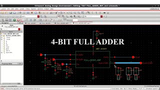
Media Summary: CADENCE - Synthesis Adder 4 bits - ARM library Virtuoso Cadence 4-bit Adder Schematic Design You can follow these Steps for any verilog program (digital

Virtuoso Cadence 4 Bit Adder Schematic Design - Detailed Analysis & Overview

CADENCE - Synthesis Adder 4 bits - ARM library Virtuoso Cadence 4-bit Adder Schematic Design You can follow these Steps for any verilog program (digital ऊपर बताया कि वो मान लोगे मैं बोला कि

Photo Gallery

Cadence Virtuoso: 4-BIT FULL ADDER Design.
CADENCE - Synthesis Adder 4 bits - ARM library
Virtuoso Cadence 4-bit Adder Schematic Design
CMOS 4 bit full adder | Schematic | Symbol | Transient response | Cadence Virtuoso
Cadence Virtuoso: Full Adder Design using Standard Logics.
Virtuoso Cadence 4-bit adder layout
4-bit adder verilog code verification using Cadence tool.
4-bit Full Adder Schematic & Layout with Hierarchal Design
4-bit Adder and Subtractor Circuit Explained
1-bit Full Adder Schematic, Layout, and Simulation
4-Bit Full Adder DC & ICC Simulation
4-Bit Adder Verilog Tutorial: Simulate & Verify Using Cadence NCLaunch
View Detailed Profile
Cadence Virtuoso: 4-BIT FULL ADDER Design.

Cadence Virtuoso: 4-BIT FULL ADDER Design.

This video explains the

CADENCE - Synthesis Adder 4 bits - ARM library

CADENCE - Synthesis Adder 4 bits - ARM library

CADENCE - Synthesis Adder 4 bits - ARM library

Virtuoso Cadence 4-bit Adder Schematic Design

Virtuoso Cadence 4-bit Adder Schematic Design

Virtuoso Cadence 4-bit Adder Schematic Design

CMOS 4 bit full adder | Schematic | Symbol | Transient response | Cadence Virtuoso

CMOS 4 bit full adder | Schematic | Symbol | Transient response | Cadence Virtuoso

In this video, we design and simulate a

Cadence Virtuoso: Full Adder Design using Standard Logics.

Cadence Virtuoso: Full Adder Design using Standard Logics.

This video demonstrates the

Virtuoso Cadence 4-bit adder layout

Virtuoso Cadence 4-bit adder layout

Virtuoso Cadence 4-bit adder layout

4-bit adder verilog code verification using Cadence tool.

4-bit adder verilog code verification using Cadence tool.

You can follow these Steps for any verilog program (digital

4-bit Full Adder Schematic & Layout with Hierarchal Design

4-bit Full Adder Schematic & Layout with Hierarchal Design

4

4-bit Adder and Subtractor Circuit Explained

4-bit Adder and Subtractor Circuit Explained

In this video, the

1-bit Full Adder Schematic, Layout, and Simulation

1-bit Full Adder Schematic, Layout, and Simulation

This is a 1-

4-Bit Full Adder DC & ICC Simulation

4-Bit Full Adder DC & ICC Simulation

Using the Synopsys

4-Bit Adder Verilog Tutorial: Simulate & Verify Using Cadence NCLaunch

4-Bit Adder Verilog Tutorial: Simulate & Verify Using Cadence NCLaunch

In this video, we'll

8 bit adder using cadence(procedure) video 4

8 bit adder using cadence(procedure) video 4

with thanks sivasankar machi Rithuparan.

CMOS 4 bit full adder using 1 bit full adder  | Schematic | Symbol | Cadence Virtuoso

CMOS 4 bit full adder using 1 bit full adder | Schematic | Symbol | Cadence Virtuoso

In this video, we design and simulate a

Day17 - Hierarchical modeling - Half-adder; Full-adder; 4-bit adder using 1-bit full adder.

Day17 - Hierarchical modeling - Half-adder; Full-adder; 4-bit adder using 1-bit full adder.

ऊपर बताया कि वो मान लोगे मैं बोला कि